I’ve ordered a bunch of capacitators and other gadets…to fix the problem.
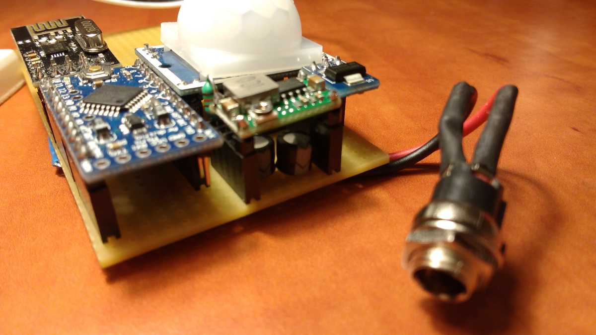
After my order arrived…i’ve moved the stepdown module to a prototyping board; and wired it up from there.
I wanted the check that the problem still exists: so i didn’t added any capacitator…and for my biggest surprise: it worked.
I thinked that: because of the different conditions…longer cabels…the noise is not that close to the other parts. I added the capacitators to the proto board…that went well to…
I soldered 100uF capacitators under the stepdown…I was happy that I have enough space to put them in…I added one for the input and one for the output..just in case.
And for my biggest surprise…when I turned it on…it didn’t worked! :) Same results…sensors good…radio doesn’t work.
I’ve ordered a few 7805 regulators to…i’ve tried out that path to on the protoboard…it worked ;)
But I didn’t wanted to start over with soldering…so: I’ve asked about how to fix this on the avr irc channel…and they recommended to use an LC filter to suppress the noise. Because I’ve already laid out the components…and I’ve used up most of my spare space under the regulator already for the caps..I didn’t know where to put the inductive part…I was a bit sad…until a bright idea came ;)
If I remove the one leg of the stepdown, i can add one of the inductor I’ve ordered!
It was not easy to remove that freaking leg…I think i even damaged the module a bit…but doesn’t matter; after a few minutes with the third hand device I was able to solder the inductor into its place…and I was lucky that when I’ve built the board: I had no 4 slot connectors…and I used a 5 slot one…i added a 120uH/.16A inductor; it doesn’t even look “very” out of place ;)
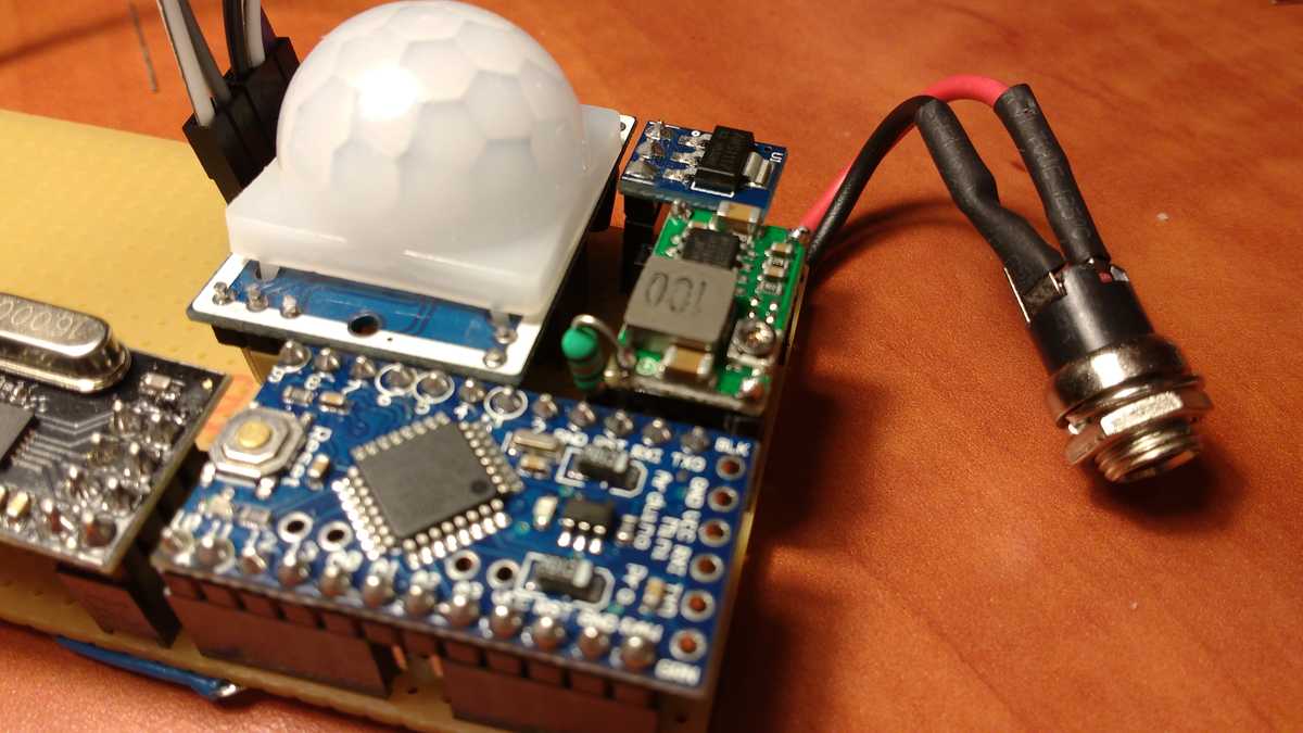
This way the device now have an LC filter on its 5V rail capable of filtering noise up to 45kHz. The stepdown uses 340kHz…more than enough. I’ve given power to it…and it worked! :)
I was curious about the power consumption ov a device like this…so: measured by my multimeter: ~30mA @ 12.4V my on desk…arduino based voltage/amp meter measured ~24-29 mA…which is not correct; but a good estimate. It’s much easier for me to keep the max471 module always in the loop…and just plug in the stuff needed to read it - instead of breaking the power circuit and adding the multimeter.
Now I can start planning the printable box’s desing.
I really enjoy working on this thing..I’m learning about very intresting electronics basics…for example: reading about how ADCs internally work was very intresting.
comments powered by Disqus